Fast, open-source DIY tester for vintage DRAM/SRAM — auto-detects the chip type, runs every test, gives a clear good/bad in seconds.
[GPL v3] [Firmware 5.0.5] · C64 · Amiga · Atari · ST · Apple II · Spectrum
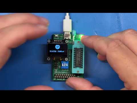
A fast, open-source DIY RAM tester for vintage RAM chips used in C64, Amiga, Atari, and other retro computers. Built around a 16MHz ATmega328P on a custom PCB, it tests memory thoroughly in seconds and supports a wide range of chip types with optional OLED feedback.
.jpeg)
As featured on:
- Adrians Digital Basement II (May 2026): "This is freaking awesome"
- Hackaday (Dec 2025): "Cheap and Aggressive DRAM Chip Tester"
- Elektor Magazine (Dec 2025): "Ram-Tester Is an Open-Source DIY Solution for Retro Computer RAM"
- No chip knowledge needed – Set the pin count via DIP switch — the tester auto-detects the chip type and runs all tests automatically. No selecting algorithms, no choosing the right socket, no menus, no datasheet lookups. Grab a chip, plug it in, get a result.
- Fast – Full test in under 8 seconds for a 41256. Test a whole tray of chips in minutes.
- Thorough – While other testers require you to choose between test modes, this one runs them all: memory patterns, crosstalk, address line verification, retention time, CAS-Before-RAS refresh, fast page mode, static column mode, ground short detection.
- Practical – Broken is broken. You get a clear good/bad result because a DRAM chip can't be repaired anyway.
- Safe – Short-circuit protection, current limiting, ground short detection. Self-test mode included.
- Fully Open Source – Hardware, firmware, schematics. No black box.
| Feature | Benefit |
|---|---|
| 20-pin ZIP socket | Direct test of 20-pin ZIP DRAMs without an adapter |
| Optional OLED display or LED blink codes | Full text feedback or minimal hardware setup |
| Self-test mode | Verify the hardware for defects like short circuits or broken solder joints |
| Capacity | DIP | 20-pin ZIP | Static Column | Nibble Mode | Retention Time | Test Time |
|---|---|---|---|---|---|---|
| 4 K × 1 | 4027 1) | – | – | – | 2 ms | 0.2 s |
| 16 K × 1 | 4816 | – | – | – | 2 ms | 0.7 s |
| 16 K × 1 | 4116 1) | – | – | – | 2 ms | 0.5 s |
| 16 K × 4 | 4416 | – | – | – | 4 ms | 1.7 s |
| 32 K × 1 | 3732 2) | – | – | – | 2/4 ms | 1.8 s |
| 32 K × 1 | 4532 2) | – | – | – | 2/4 ms | 1.8 s |
| 64 K × 1 | 4164 | – | – | – | 2/4 ms | 1.8 s |
| 64 K × 4 | 4464 | – | – | – | 4 ms | 5.2 s |
| 256 K × 1 | 41256 | – | – | 41257 | 4 ms | 7.5 s |
| 256 K × 4 | 44256 | both | 44258 | – | 8 ms | 3.5 s |
| 1 M × 1 | 411000 | ✗3) | – | – | 8 ms | 23.8 s |
| 1 M × 4 | 514400 | both | 514402 | – | 16 ms | 12.0 s |
1) Requires the 4116 adapter board.
2) Half-good 4164 chips sold as 32K × 1 (OKI MSM3732 / TI TMS4532). Enabled by default since firmware 4.2.3. See 32K documentation for details.
3) The ZIP pinout is different than the 20-pin DIP — for the ZIP version you need an adapter!
Static Column means the RAM allows column changes while CAS is held low — faster than standard page mode. Nibble Mode delivers four consecutive bits from one column address.
| Capacity | DIP | Test Time |
|---|---|---|
| 1 K × 4 | 2114 1) | 0.4 s |
1) WARNING: 2114 SRAM needs to be inserted 180° rotated, with Pin 10 of the SRAM on the ZIF Pin 1 marking.
- Insert the device (16, 18 or 20 pins, DIP or ZIP).
- Set the DIP switch to match the pin count of your RAM. See the operation manual for the switch settings.
- Connect USB power supply (or press RESET if already powered).
- Read the result
- OLED version: plain-text report on the display
- LED-only version: green = pass, red = fail
There is a short YouTube video demonstrating the tester in action.
- GND shorts — checks if any pin is shorted to ground
- Power supply shorts — a resettable fuse protects the board
- Address-line and decoder faults
- Stuck cells or crosstalk via bidirectional Checkerboards
- Random patterns combined with retention time checks
- CAS-before-RAS refresh timer function
- All of the above use the appropriate access mode for the chip type: Fast Page Mode, Static Column, or Nibble Mode
Here is the analytics of this algorithm vs. March-B
| Aspect | This Tester | MARCH-B |
|---|---|---|
| Pattern Coverage | ✅ Checkerboard | ✅ |
| 0→1 / 1→0 Transition | ✅ Via pattern sequence | ✅ Via R0W1, R1W0 |
| Address Sequence | ✅ Asc + Descending | ✅ Asc + Descending |
| Coupling Detection | ✅ Via retention delay | ✅ Systematic |
| Real Retention | ✅ 2–16 ms per chip spec | ❌ Not covered 1) |
| GND Short Detection | ✅ Before test | |
| Address Line Faults | ✅ Bit-independence check | |
| CBR Refresh | ✅ CAS-before-RAS test2) | ❌ Not covered 1) |
1)unless implemented outside of MARCH-B
2)For RAM that have a Refresh Counter (41256 and newer)
March-B is thorough for coupling and decoder faults but operates in the microsecond range — it cannot catch chips with weak retention that meet spec on paper but fail under real-world refresh timing. This tester trades systematic address ordering for real-time retention stress, which is where most age-related failures actually occur.
Vintage DRAM chips were designed for TTL signal levels. The ATmega328P drives CMOS levels at 5 V — logic high is close to VCC, which is above what the original systems delivered. This means marginal chips that fail at true TTL thresholds may still pass on this tester (and most other microcontroller-based testers). Some designs use 3.3 V controllers with 5 V-tolerant I/O to get closer to TTL levels, but the ATmega328P does not support this operating mode. In practice, virtually no consumer DRAM tester on the market operates at true TTL levels — this is a fundamental limitation of the approach, not specific to this project. For definitive TTL-level testing, dedicated vintage test equipment (e.g. Advantest, Agilent) operating at calibrated thresholds would be needed.
Buy ready-made: Amibay · Lectronz · eBay
Build it yourself (DIY): Available as a beginner-friendly through-hole (THT) version or a compact SMD version. Order PCBs at PCBWay (THT) or use the provided Gerber files from the Schematic folder.
- Operation manual – test procedure, error codes, self-test and troubleshooting
- Software / Firmware – firmware variants, flashing instructions
- Schematic – KiCad project and Gerber files (THT and SMD)
- Changelog – firmware version history
- Compatibility – manufacturer cross-reference and system DRAM/SRAM usage
You're welcome to build, modify and even sell your own Ram-Testers — that's the point of open hardware. In return, the license asks you to keep it open:
- It stays open-source. Boards you distribute or sell remain under CERN-OHL-S v2 (hardware) and GPL v3 (firmware). No closing the design, no proprietary fork.
- Pass on the source. If you sell or give away boards, make the complete design files for your version — including any changes you made — available under the same license.
- Keep the credit and the link. Leave the copyright and license notices intact and keep the source location — https://github.com/tops4u/Ram-Tester/ — visible, on the board silkscreen where practicable (CERN-OHL-S §4).
- Don't strip attribution. Selling it as your own closed product, or removing the notices, is not permitted.
- Article description. For online platforms you need to include: Creator, link to the source files (this GitHub repo) and licence.
In short: build it, improve it, sell it — just keep it open and point people back here. If unsure, open a Discussion and ask.
Pull requests, issues and forks are welcome. Questions: GitHub Discussions or contact tops4u on AmiBay.
Open-source hardware (CERN-OHL-S v2) and firmware (GPL v3) – use at your own risk.